Aluminum alloy TIG and MIG welding process analysis: technology comparison, operation points and industry applications
Date: 2025-05-17 Categories: Blog Views: 953
Challenges and Importance of Aluminum Welding
aluminum Due to its light weight, high strength and corrosion resistance, it is widely used in automotive, aerospace and shipbuilding. However, its high thermal conductivity, oxidizability and sensitivity to thermal cracks make the welding process face serious challenges. TIG and MIG welding technology provides an efficient solution to the need for high strength and airtightness of welded seams in battery trays for new energy vehicles, for example.
Aluminum Features:
small density:: Aluminum alloys have a lower density than steel and copper, about 2.7 g/cm3, so aluminum alloy products are lighter than steel products of the same volume.
high strength: Aluminum alloys have high strength and hardness, which can be significantly improved by heat treatment.
Good conductivity: Aluminum alloys have better electrical conductivity than pure copper and steel and can be used to make conductive materials such as wires and cables.
Good corrosion resistance: The surface of aluminum alloy easily forms a dense oxide film, which has good corrosion resistance.
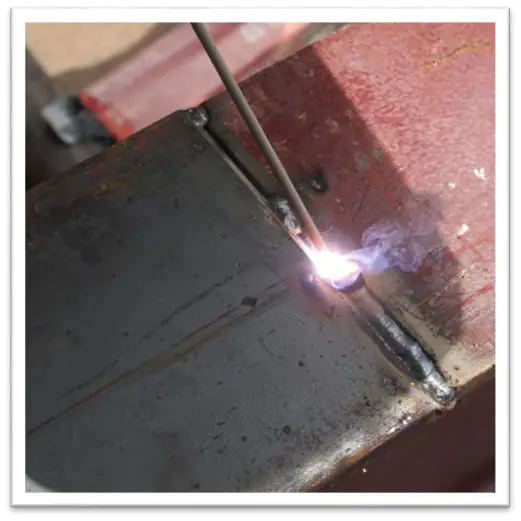
TIG welding technology in detail
Process principle and equipment configuration
TIG welding (tungsten inert gas shielded welding) uses a non-fused tungsten electrode to form a molten pool under the protection of inert gas (argon or helium). AC TIG welding machine can effectively remove the oxide film (Al?O?) on the surface of aluminum alloy through cathodic crushing effect, which is suitable for welding of aluminum alloy of Series 6 (such as 6061) and Series 5 (such as 5052).
Operating points and parameter settings (6061 aluminum alloy as an example)
- Pre-welding treatment:
- Acetone cleaning to remove oil, stainless steel wire brush mechanical sanding oxidation layer (prohibit sandpaper to prevent carbon contamination).
- Welding parameters:
- Current: 80-200A (AC pulse mode, base current accounts for 30%).
- Tungsten electrode: Cerium tungsten electrode (diameter 2.4mm, tip ground at 30° cone angle).
- Protective gas: argon (purity ≥99.99%), flow rate 10-12L/min.
- Choice of filler wire: ER4043 (silicon content 5%, good crack resistance) or ER5356 (magnesium content 5%, high strength).
Strengths and limitations
- dominance: Beautiful, spatter-free weld seams, suitable for thin plates (1-3mm) and precision components (e.g. electronic heat sinks).
- limitations: Slow welding speed (about 0.3m/min) and high labor cost.
MIG welding technology in detail
Process principle and equipment selection
MIG welding (melting electrode inert gas shielded welding) adopts a continuous wire feeding mechanism, which is suitable for welding medium-thick plates. Push-pull wire feeding system can solve the problem of poor wire feeding caused by the softness of aluminum alloy wires (e.g. ER5183). The gas mixture (Ar+He) improves arc stability and reduces porosity.
Operation points and parameter settings (take 5083 aluminum alloy as an example)
- Pre-welding treatment:
- Thick plates (>10mm) need to be preheated to 80-120°C (to reduce the risk of thermal cracking).
- Bevel design: V-bevel (angle 60°-70°), blunt edge 1-2mm.
- Welding parameters:
- Current: 220-260A (double pulse mode, low-frequency pulse to reduce splash).
- Voltage: 24-26V, wire feeding speed 8m/min.
- Protective gas: Ar (80%) + He (20%), flow rate 18-20L/min.
Strengths and limitations
- dominance: High efficiency (speed up to 1.2m/min), suitable for mass production of long weld seams such as automobile chassis.
- limitations: Spatter control is difficult (pulse parameters need to be optimized) and the initial investment in equipment is high (about 500,000 RMB for the robot system).
TIG vs MIG: Process Selection Guide
| comparison term | TIG welding | MIG Welding |
|---|---|---|
| Applicable thickness | 1-6mm (sheet) | 3-25mm (medium and thick plates) |
| Weld quality | High precision, no splash | High efficiency, splash needs to be controlled |
| (manufacturing, production etc) costs | Labor cost as a percentage of 60% | Equipment and Consumables Cost Ratio 70% |
| typical application | Aerospace skins, electronic housings | Ship decks, automotive structural parts |
Welding defect prevention, control and inspection standards
5.1 Solutions to common defects
- stoma: Ensure the purity of the protective gas (argon dew point ≤ -50℃) and thoroughly clean the base metal before welding.
- thermal crack: Select ER5356 wire with high Mg content (Mg/Si>1.5) and control the interlayer temperature <100℃.
- unfused: Increase the current 10%-15% and reduce the welding speed to 0.8m/min (MIG welding).
5.2 Detection methods
- Visual inspection (VT): Detection of cracks and edges on the surface of the weld with reference to ISO 10042.
- X-ray inspection (RT): According to the requirements of AWS D1.2, the diameter of air holes ≤ 1.5mm is qualified.
6. Frequently Asked Questions (FAQ)
Q1: Can TIG welding be used to weld aluminum alloys with DC power?
- NO! DC TIG will not break up the oxide film, AC power must be used.
Q2:How to solve the problem of high spatter in MIG welding?
- Change to double pulse mode, reduce peak current (example: from 300A to 260A) and increase helium ratio to 30%.
Q3: Is heat treatment required after welding?
- 6 series aluminum alloys (such as 6061) need to be solid solution treatment after welding (530 ℃ × 2h water quenching + 180 ℃ × 8h aging) to restore strength.